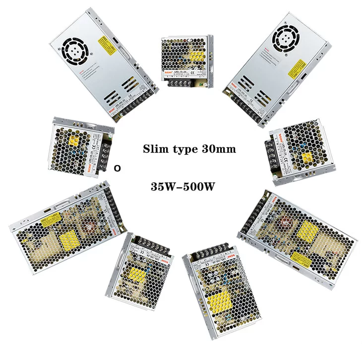
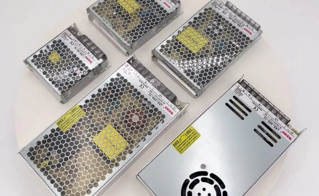
Switching Mode Power Supply (SMPS), ubiquitous in modern electronics, represent a paradigm shift from traditional linear power supplies. Their ability to achieve high efficiency, compact size, and versatile voltage conversion has made them indispensable in applications ranging from mobile chargers to industrial power systems. For those of us captivated by power electronics, understanding the inner workings of SMPS is key to appreciating their elegance and effectiveness. This post will dissect the fundamental principles and key components that enable SMPS to perform their power conversion magic.
The Core Concept: Switching and Energy Storage
Unlike linear power supplies, which regulate voltage by dissipating excess power as heat, SMPS operate on a fundamentally different principle: controlled switching and energy storage. Instead of continuously conducting, SMPS use semiconductor switches (MOSFETs, IGBTs, BJTs) to rapidly switch the input voltage on and off. This switching action, combined with energy storage elements (inductors and capacitors), allows for efficient voltage conversion and regulation.

Key Stages of a Switch-Mode Power Supply
A typical SMPS consists of several key functional stages:
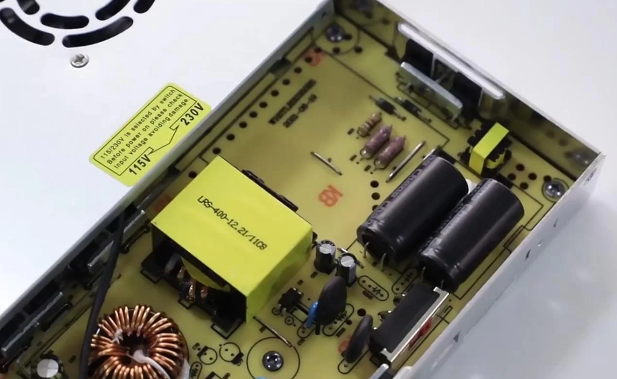
Input Rectification and Filtering: The AC input voltage is first rectified to DC using a diode bridge or an active rectifier. This DC voltage is then filtered using capacitors to reduce ripple. In universal input SMPS, this stage might include a voltage doubler or a switch to configure the rectifier for different AC input ranges.
Switching Stage: This is the heart of the SMPS, where the DC voltage is chopped into a high-frequency pulsed waveform using a power semiconductor switch. The switch is controlled by a pulse-width modulation (PWM) signal, which determines the duty cycle (on-time versus off-time) of the switch.
Transformer (in Isolated Topologies): For applications requiring electrical isolation between input and output, a high-frequency transformer is used. The transformer also provides voltage scaling, stepping the voltage up or down as needed.
Output Rectification and Filtering: The pulsed voltage from the switching stage or transformer secondary is rectified using diodes (Schottky diodes for higher efficiency in low-voltage applications) or synchronous rectifiers (MOSFETs acting as rectifiers for even higher efficiency). The rectified voltage is then filtered using inductors and capacitors to produce a smooth, stable DC output.
Feedback and Control Circuitry: A feedback loop monitors the output voltage and compares it to a reference voltage. The error signal is used to adjust the PWM signal, regulating the output voltage and maintaining it at the desired level. This closed-loop control system is essential for maintaining stable output voltage under varying load and input conditions.

Fundamental Switching Topologies
Various switching topologies are employed in SMPS, each with its own advantages and disadvantages:
Buck Converter (Step-Down): This topology reduces the input voltage to a lower output voltage. It’s widely used for voltage regulation and point-of-load (POL) applications.
Boost Converter (Step-Up): This topology increases the input voltage to a higher output voltage. It’s often used in power factor correction (PFC) circuits and applications requiring a voltage higher than the available input.
Buck-Boost Converter (Inverting or Non-Inverting): This topology can produce an output voltage that is either higher or lower than the input voltage. It’s useful when the input voltage may vary above and below the desired output voltage.
Flyback Converter: An isolated topology suitable for lower power applications, offering simplicity and cost-effectiveness.
Forward Converter: Another isolated topology, generally more efficient than flyback for higher power levels.
Half-Bridge and Full-Bridge Converters: These isolated topologies are used for higher power applications, offering high efficiency and good utilization of transformer core material.
Resonant Converters (LLC, Series, Parallel): These topologies use resonant switching techniques to minimize switching losses, enabling higher switching frequencies and improved efficiency.
Pulse-Width Modulation (PWM) Control
PWM is the cornerstone of SMPS control. By varying the duty cycle of the switching signal, the average voltage delivered to the output can be precisely controlled. Different PWM control schemes exist, each offering specific performance characteristics:
Voltage-Mode Control: A simple and widely used control scheme where the feedback loop regulates the output voltage directly.
Current-Mode Control: This scheme regulates the inductor current, offering better transient response and inherent overcurrent protection.
Hysteretic Control: A simple control method where the switch turns on and off based on predefined upper and lower thresholds of the output voltage or current.
Efficiency Considerations in SMPS Design
Achieving high efficiency is a primary goal in SMPS design. Losses occur in various components:
Switching Losses: Power dissipated during the switching transitions of the semiconductor switches.
Conduction Losses: Power dissipated due to the on-resistance of the switches and the resistance of other components.
Magnetic Losses: Core losses and copper losses in inductors and transformers.
Capacitor Losses: Equivalent series resistance (ESR) losses in capacitors.
To minimize these losses, designers employ various techniques:
Soft Switching: Techniques like zero-voltage switching (ZVS) and zero-current switching (ZCS) reduce switching losses by ensuring that switching transitions occur when either voltage or current is zero.
Synchronous Rectification: Replacing diodes with MOSFETs for rectification reduces conduction losses.
Low-ESR Capacitors: Using capacitors with low equivalent series resistance minimizes power losses in the output filtering stage.
Optimized Magnetic Component Design: Careful selection of core materials and winding techniques minimizes magnetic losses.
Wide Bandgap Semiconductors (SiC, GaN): Utilizing silicon carbide (SiC) or gallium nitride (GaN) MOSFETs enables higher switching frequencies, lower switching losses, and higher operating temperatures.
 Conclusion: The Power and Elegance of Switching
Switch-mode power supplies represent a sophisticated and elegant approach to power conversion. By harnessing the principles of controlled switching and energy storage, SMPS achieve unparalleled efficiency, compactness, and versatility. For those of us passionate about power electronics, understanding the intricate workings of these circuits is not only intellectually stimulating but also essential for pushing the boundaries of power conversion technology. As the demand for efficient and reliable power continues to grow, switch-mode power supplies will remain at the forefront of innovation, powering the devices and systems that shape our modern world.


