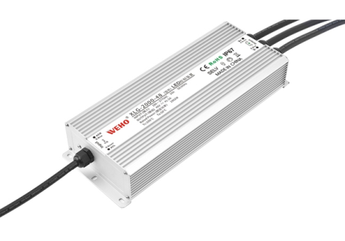
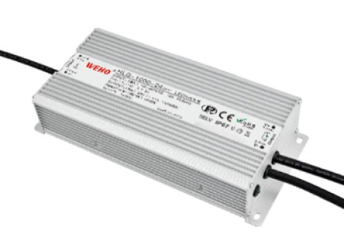
What is a power supply?
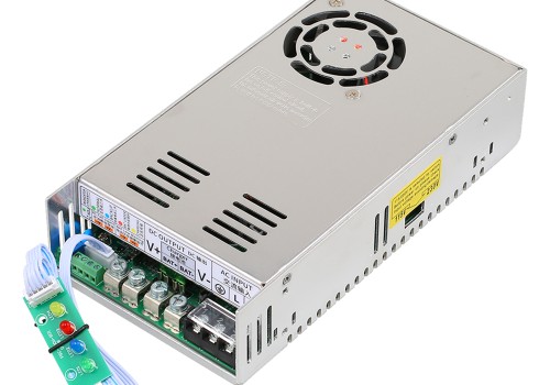
A power supply is an electrical device, it converts the current that comes from the power supply to the voltage value required by the load, such as an electronic motor or an electronic device.
There are two main designs for power supplies: a linear power supply and a switching power supply.
Linear: Linear power supply designs use a transformer to lower the input voltage. Then the voltage is rectified into DC voltage and then filtered to improve the waveform quality.
Linear power supplies use linear regulators to maintain a constant voltage at the output. These linear regulators dissipate any additional energy in the form of heat.
Switching: Switching power supply design is a relatively new method, It is designed to solve many problems associated with linear power supply design, including transformer size and voltage regulation.
In switching power supply designs, the input voltage is no longer reduced. Instead, it’s calibrated and filtered at the input. Then the voltage goes through a chopper, which converts it into a high-frequency pulse train. Before the voltage reaches the output, it’s filtered and rectified once again.
Topology of switching power supply
Switching power supplies (SMPS) have four topologies, such as AC-DC converter, DC-DC converter, Fly-back Converter, and Forward Converter.
AC-DC converter: In this type of SMPS, the input power is AC and the output power is DC. we get DC supply. Rectifiers and filters are used to convert this alternating current to a direct current.
DC-DC converter: The input power of this power supply is directly from the high voltage DC power directly.
Fly-back Converter: Any SMPS with output power less than 100W is called flyback converter SMPS. Compared to other SMPS, the circuit of these SMPS is simple and straightforward. This type of SMPS is used for low power consumption.
Forward Converter: The design of this type of SMPS is almost identical to the anti-shock converter SMS. In this SMPS, the switch is connected to the output of the transformer secondary winding for control.
Compared with flyback converters, filtering and correction circuits are more complex. These SMPS, also known as DC-DC buck converters, are also used for transformer scaling and isolation.
How does a switching power supply work?
Over the years, linear AC/DC power supplies have played a crucial role in converting AC power from the utility grid into DC voltage, catering to the energy needs of home appliances and lighting. However, as technology advanced, the landscape shifted, especially in high-power applications. Linear power supplies, known for their low noise, found a niche in specific industrial and medical applications. Despite their merits, the dominance of switching power supplies became evident due to their smaller size, increased efficiency, and capability to handle high power. The process of power conversion typically involves three stages: input rectification, power factor correction (PFC), and isolation. Figure 1 provides an overview of the general conversion from alternating current (AC) to direct current (DC) in a switching power supply.
A switching power supply, being an electronic power supply, incorporates a switching regulator designed for efficient electricity conversion. Similar to other power supplies, Switched-Mode Power Supplies (SMPS) transfer power from a DC or AC source, typically the mains, to a DC load, such as a personal computer. During this process, voltage and current characteristics are simultaneously adjusted to meet the load requirements.
In the realm of switching power supplies, the pass transistor undergoes continuous transitions between low-power, fully-on, and fully-off states. This dynamic behavior minimizes time spent in highly dissipative transitions, effectively reducing energy waste. In an ideal scenario, a switch-mode power supply consumes no power, making it a compelling choice for energy-efficient applications.
Input rectification
The process of rectification involves the conversion of AC voltage into DC voltage. In the context of a switch-mode AC/DC power supply, the initial stage is input signal rectification. While it is commonly perceived that DC voltage resembles a stable, unchanging line akin to that produced by a battery, it’s crucial to recognize that direct current (DC) is characterized by a unidirectional flow of electrical charge. This implies that the voltage flows consistently in the same direction but does not necessarily remain constant.
To accomplish rectification in the context of a switch-mode power supply, a passive half-bridge rectifier can be employed to eliminate the negative half of the sine wave through a diode (refer to Figure 2). The diode permits current to flow during the positive half of the wave but blocks it when the flow is in the opposite direction. This selective flow control ensures the conversion of AC voltage into a more unidirectional DC voltage, a fundamental step in the power supply’s operation.
Following the rectification process, the resulting sine wave possesses a low average power, rendering it insufficient for effectively powering the device. To enhance efficiency, an alternative method involves altering the polarity of the negative half-wave, transforming it into a positive wave. Known as full-wave rectification, this technique can be achieved with a bridge configuration employing four diodes (refer to Figure 3). The strategic arrangement of these diodes ensures a consistent current direction, irrespective of the polarity of the input voltage. This configuration contributes to maintaining a stable power supply for the device.
While the fully rectified wave yields a higher average output voltage compared to that of the half-bridge rectifier, it still deviates from the ideal constant DC waveform necessary for powering electronic equipment. Despite being a form of DC, its utilization for device power is inefficient due to the rapid and frequent changes in the voltage wave’s value. This fluctuation in DC voltage, known as ripple, poses a challenge to an efficient power supply.
To address this issue, the most straightforward and widely employed method involves the integration of a large capacitor at the rectifier output, often referred to as a storage capacitor or smoothing filter (refer to Figure 4).
This capacitor plays a pivotal role in smoothing out the voltage waveform by storing voltage during the peak of the wave and subsequently supplying current to the load until its voltage falls below the rising rectified voltage wave. The resultant waveform closely approximates the desired shape, resembling a DC voltage without an AC component. This refined voltage waveform becomes suitable for powering DC devices.
Passive rectification, employing semiconductor diodes as uncontrolled switches, stands as the simplest method for rectifying AC waves, yet it falls short in terms of efficiency.
Although diodes serve as relatively efficient switches, capable of swift on-off transitions with minimal power loss, they are hindered by a forward bias voltage drop ranging from 0.5V to 1V, contributing to reduced efficiency.
Active rectification takes a different approach by replacing diodes with controlled switches, such as MOSFETs or BJT transistors (refer to Figure 5). This approach offers a dual advantage: firstly, transistor-based rectifiers eliminate the fixed 0.5V to 1V voltage drop characteristic of semiconductor diodes, as their resistance can be arbitrarily small, resulting in a significantly reduced voltage drop.
Secondly, transistors, functioning as controlled switches, allow for the optimization of switching frequency, providing flexibility. However, it comes at the cost of increased complexity in control circuitry for active rectifiers, involving additional components and making them comparatively more expensive.
Power factor correction
The second stage of switching power supply design is power factor correction.
Observing the current waveform of the rectifier storage capacitor (refer to Figure 6), it becomes apparent that the charging current rapidly traverses the capacitor, particularly when the input voltage from the capacitor surpasses the peak charge of the rectified signal. This rapid charging process generates a series of short current spikes in the capacitor, posing not only challenges for the power supply but also presenting issues for the entire grid. The abrupt current spikes introduce a significant number of harmonics into the grid, leading to distortion that can adversely affect other power supplies and equipment connected to the grid.
In the realm of switching power supply designs, the power factor correction circuit aims to mitigate these harmonics by effectively filtering them out. Two primary options exist for achieving this: active power factor correction and passive power factor correction.
Passive power factor correction involves the incorporation of passive low-pass filters designed to eliminate high-frequency harmonics. However, power supplies relying solely on passive PFCs, particularly in high-power applications, struggle to comply with international regulations on harmonic noise. As an alternative, active power correction becomes necessary.
Active power factor correction works by reshaping the current waveform to align with the voltage waveform. This adjustment relocates the harmonics to higher frequencies, facilitating their easier filtration. In such scenarios, the boost converter, also known as a boost converter, emerges as the widely employed circuit for effective active power factor correction.
Isolation: Isolated vs. non-isolated switching power supplies
With the rectification of the input AC waveform at the input end, the resulting output DC voltage becomes notably elevated. In the absence of Power Factor Correction (PFC), the rectifier yields an output of approximately 320V. Introduction of an active PFC circuit, however, transforms the output of the boost converter into a stable DC voltage reaching 400V or higher.
Both scenarios, characterized by excessively high DC voltages, pose significant risks and prove impractical for the majority of applications that typically demand much lower voltage levels. Table 1 outlines various aspects related to converters and applications that merit consideration when selecting the appropriate isolation topology. This comprehensive overview aids in making informed decisions based on specific requirements and safety considerations.
Advantages of switching power supply
The use of any technology is often a careful balance of several advantages and disadvantages. This is true for switch-mode power supplies which offer some distinct advantages but also have their drawbacks.
SMPS advantages
High efficiency: A switch action means that the series regulator element is on or off. So very little energy is given off as heat, and very high levels of efficiency can be achieved.
Compact: Due to high efficiency and low heat dissipation level, Switching mode power supplies can be made more compact.
Costs: One of the things that makes switching power very attractive is cost. The higher efficiency and switching characteristics of the design mean that less heat is required than a linear power supply, resulting in lower costs. Over time, the switching nature of the power supply means that many components cost less.
Flexible technology: Switching power supply technology can be used to provide high-efficiency voltage conversions in voltage step-up or “Boost” applications or step-down “Buck” applications.
On balance, switching power supplies are ideal for a host of applications from computers to chargers, and laboratory equipment to many items of domestic electronic gadgetry. Cost, size, and efficiency are key factors in ensuring that they become a major technology for many applications.
Applications of SMPS:
For many years, Linear AC/DC power supplies have been converting alternating current from the utility grid to DC voltage, and fit is used to run household appliances or lighting. High-power applications require smaller power supplies.
This means that linear power supplies have been relegated to specific industrial and medical uses. Because of their low noise, they are still needed in these uses. But switching power supplies have taken over because they are smaller, more efficient, and capable of handling high power.
Switching power supplies have many applications, such as computers which are the most common use, security systems, railway systems, battery chargers, and machine tool industries.
Switching power supply is widely used downstream. Recently, switching power supply has become more and more important in the LED industry, medical equipment, mobile phone charger, automobile, consumer electronics, and other fields.
Globally, the switching power supply market is driven primarily by the growing demand for consumer electronics, which accounted for nearly 52% of the total downstream consumption of SWITCHING power supplies.
Summary
There are many different aspects to consider when designing a switching power supply, especially related to safety, performance, size, weight, and so on. Switching power supplies also have more complex control circuits than linear power supplies, which is why many designers find it useful to implement integrated modules in their power supplies.
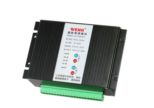
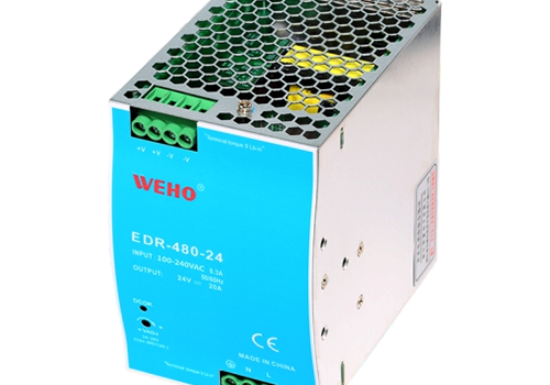
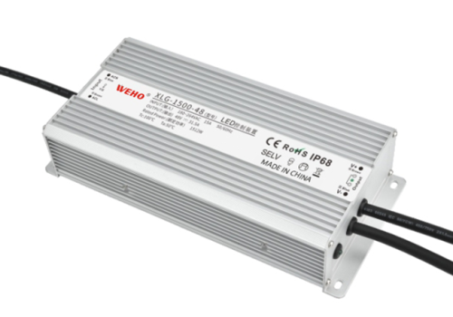
WEHO offers a wide variety of modules that can simplify switching power supply design, such as NDR EDR Din-rail Power supply, LRS Slim type power supply, LPV IP67 Waterproof LED drive, DC-DC converter, etc.


